
In: AIAA 37th Aerospace Sciences Meeting and Exhibit, Reno, Nevada, pp. Ramamurti, R., Sandberg, W.: Simulation of flow about flapping airfoils using finite element incompressible flow solver. Hover, F.S., Haugsdal, O., Triantafyllou, M.S.: Effect of angle of attack profiles in flapping foil propulsion. Read D.A., Hover F.S., Triantafyllou M.S.: Forces on oscillating foils for propulsion and maneuvering. Taylor G.K., Nudds R.L., Thomas A.L.R.: Flying and swimming animals cruise at a Strouhal number tuned for high power efficiency. Triantafyllou G.S., Triantafyllou M.S., Grosenbaugh M.A.: Optimal thrust development in oscillating foils with application to fish propulsion. Koochesfahani M.M.: Vortical patterns in the wake of an oscillating airfoil. Shyy W., Lian Y., Tang J., Liu H., Trizila P., Stanford B., Bernal L., Cesnik C., Friedmann P., Ifju P.: Computational aerodynamics of low Reynolds number plunging, pitching and flexible wings for MAV applications. Phase difference between pitching and heaving, in degrees θ 0 These results aid in the design of a better ornithopter’s wing. Overall, the S1020 airfoil is able to provide relatively good efficiency and at the same time generate high thrust and lift force.

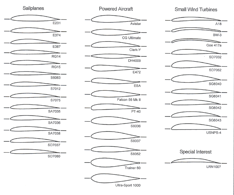
Vorticity diagrams are analyzed to explain the results obtained. This shows that it is not sufficient to analyze each variable individually. Two-factor interactions are found to exist among the variables. The lift production is highly dependent on the airfoil’s shape while thrust production is influenced more heavily by the variables. The average thrust coefficient and efficiency also reach high values of 2.53 and 0.61, respectively. By using non-symmetrical airfoils, average lift coefficient as high as 2.23 can be obtained. Results show that both the variables and shape of the airfoil have a profound effect on the lift, thrust, and efficiency. In order to analyze the variables more efficiently, the design of experiments using the response surface methodology is applied. The variables involved are reduced frequency, Strouhal number, pitch amplitude and phase angle. angle of attack), making analysis simpler.Simulations have been done to assess the lift, thrust and propulsive efficiency of different types of non-symmetrical airfoils under different flapping configurations.

The aerodynamic center is the point at which the pitching moment coefficient for the airfoil does not vary with lift coefficient (i.e. In aerodynamics, the torques or moments acting on an airfoil moving through a fluid can be accounted for by the net lift and net drag applied at some point on the airfoil, and a separate net pitching moment about that point whose magnitude varies with the choice of where the lift is chosen to be applied. The aerodynamic center is shown, labeled "c.a." This diagram shows only the lift components the similar drag considerations are not illustrated. This image shows the forces for two typical airfoils, a symmetrical design on the left, and an asymmetrical design more typical of low-speed designs on the right. The distribution of forces on a wing in flight are both complex and varying.


 0 kommentar(er)
